The Thanksgiving Comet 2013

Figure 1 - From the Bayeux Tapestry (c 1070), the appearance of Halley's Comet in 1066 AD brings fear to the minds of the troops of William the Conquerer.  Image uploaded by Mirabella to the Wikipedia Commons and in the public domain.

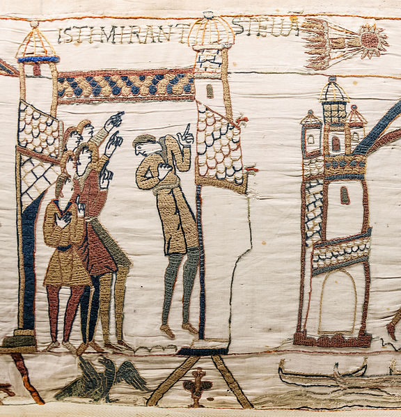
Figure 1 – From the Bayeux Tapestry (c 1070), the appearance of Halley’s Comet in 1066 AD brings fear to the hearts and minds of the troops of William the Conqueror. Image uploaded by Mirabella to the Wikipedia Commons and in the public domain.

Well here’s something unusual – a technical blog.  What can I say, I’ve gotten just a bit lazy.  But I do want to point out that on Thanksgiving Day, November 28, 2013 comet ISON is going to whip around the sun, aka reach its perihelion.  If it doesn’t completely vaporize, which is pretty unlikely since this is what comets do, it may produce a truly spectacular show in December and January.  This means, of course, that you are going to want to photograph it, and I am going to tell you how.

First of all, I am going to assume that you do not have a telescope with celestial clock drive.  A celestial clock drive is a computer driven motor that enables you to point your telescope at a sky object, and it will follow the object as the sky moves.  BTW – they worked pretty well in the analogue days before computers – better living through physics.  If you have one of these, you probably don’t need me to tell you how to use it.  Second, this could turn into a pretty big object, in which case a telescope isn’t necessary.  It all depends, and that’s the key.  Nobody really knows what we are in for.  But it is likely that the best shots are going to be taken with a moderate telephoto or zoom lens.  I’m hesitant to conjecture, but maybe 200 to 400 mm.

So here you go:

1. Find a place away from city lights.  That’s the tricky part because these are going to be several second exposures, and you don’t want the background of the sky to outshine the comet.  This also makes just after perihelion a bear of a time to photograph.  At that point comet ISON is going to be in the early morning sky, hovering below the horizon.  Also at these early points, do I have to say this, DON’T LOOK DIRECTLY AT THE SUN.  I have a feeling that the best times are going to be mid-December to early January.

2.Moderate zoom lens

3. Lens wide open aka smallest f-number

4. You need a tripod

5. Image stabilized lens recommended because of wind.

6. Manual focus preferred – despite the fact that the thing is at infinity

7. ISO of at least 800

8. Lock your mirror up to avoid shake

9. Exposure will be several seconds, depending on events again.  This is probably best done with manual shutter speed and bracketing.

This should be all you need to know.  Happy shooting.

Figure 2 - Comet ISON photographed by the robotic eyes of the Hubble Space Telescope on October 9, 2013.  From NASA and in the public domain.

Figure 2 – Comet ISON photographed by the robotic eyes of the Hubble Space Telescope on October 9, 2013. From NASA and in the public domain.

The glory of partially diffuse light

Figure 1 - Morning light diffused through sheer curtains, (c) DE Wolf 2013.

Figure 1 – Morning light diffused through sheer curtains, (c) DE Wolf 2013.

Yesterday, I was doing what photographers do, namely experimenting with semidiffuse light.  Let’s start with a few definitions.  Suppose that you are out on a bright cloudless day.  The sun acts as a point source of light, just like a flashlamp.  As a result, you get sharp shadows, which generally translates to high contrast in your photographs.  This is nondiffuse light.  Such light sources tend to create specular reflections off  mirror like or shiny surfaces.  On the other hand, if the sun is shining through clouds the light is bounced around until it is coming at you from all directions.  There’s another way to create a diffuse light and that is by bouncing the light off a rough surface. Both of these reduce the contrast in the image.

Figure 2 - Carpet shadows, (c) DE Wolf 2013.

Figure 2 – Carpet shadows, (c) DE Wolf 2013.

So, what I’ve said is that there are two ways to diffuse or soften the light.  First, you can pass it through a scattering medium like a cloud.  Second, you can bounce it off a rough scattering surface.

Things can get really interesting when you start to work with semidiffuse light.  Yesterday, I took the photograph in Figure 1, of highly intense directional light being diffused as it passed through sheer curtains.  Notice how you can just make out some of the details behind the curtains, but that they are just a bit cloudy.  The intensity of the light and its diffusion creates a very dreamy illumination that, to me anyway, screams out “morning.”

Figure 2, on the other hand, uses light that has filtered through a forest of leaves, thus losing some of its directionality.  The shadows of the leaves and the window frame are fuzzed out.  The light is then further diffused by the texture of the carpet.  All in all it creates a very abstract sense.

Figure 3 - Morning fog at Brigham Farm, Concord, MA, (c) DE Wolf 2013.

Figure 3 – Morning fog at Brigham Farm, Concord, MA, (c) DE Wolf 2013.

Figure 3 combines both types of light.  It is an early morning scene, taken a couple of weeks ago on my commute to work.  The light is early morning light and very direct.  Notice the sharply illuminated dew on the plants.  But then notice how the morning fog diffuses the light creating dramatic sunbeams.

I am hoping that I have demonstrated the point that semidiffuse light can create very dramatic effects.  And when you are really successful these effects can be quite magical.

The power of catch light

Figure 1 - Witch without catchlight, (c) DE Wolf 2013.

Figure 1 – Witch without catchlight, (c) DE Wolf 2013.

Recently I posted a series of Halloween photographs.  When I started this project, I took the image shown in Figure 1.  She is a happy witch, not menacing, but something seems wrong with the photograph.  Somehow the witch is listless and unlifelike.  The reason for this is that her eyes lack the phenomenon of “catch light,” which is, simply put, the reflection of the illuminating light off the cornea of the eyes.  The cornea is the clear, wet surrounding layer. Catch light is essentially the sparkle in one’s eyes. The most common form of catch light is that which forms from a flash.  Since flashes usually are, like the sun, point sources of light, the catch light often appears as a bright dot in the dark center of the eye, within the pupil.

Take a look at Figure 2, which a funerary portrait of a young Egyptian boy.  I chose this image because it is nearly two thousand years old.  So while it is not a photograph it is still pretty lifelike, and the two catch light bright spots in the eyes really brings the boy to life, or back to life.

Figure 2 - Funerary portrait of a young Egyptian boy,  From the Wikimedia Commons originally uploaded by Juanmak and in the public domain.

Figure 2 – Funerary portrait of a young Egyptian boy, From the Wikimedia Commons originally uploaded by Juanmak and in the public domain.

Catch light does not have to be bright spots.  This is shown in Figure 3.  Indeed, the eyes are portals to the soul and mirror whatever is in front of them.  This has been used to great effect in several mystery stories where the plot hinges on blowing up the catch light to reveal the “murderer” or other detail in the mystery,

Catch light has played an important role in the movies.  Directors often light up the sparkle in the eyes of starlets to make them more vibrant and glamorous, for instance Ingrid Bergman in “Casablanca.”  On the other hand, catch light is removed from the eyes of bad guys to create a sense, like our witch and others in my Halloween series, of the sinister and ominous.

So what about our witch.  Since I wanted a happy lifelike witch I use Adobe Photoshop to add two catch light spots to her eyes. I have also used the same trick when I remove red eye.  The process of removing red eye often simultaneously removes catch light and re-adding it with little bright spots adds to the

Figure 3 - Baby with sparkle or catch light in its eyes.  From the Wikimedia Commons original by Christine B. Szeto and put into the public domain under creative commons license.

Figure 3 – Baby with sparkle or catch light in its eyes. From the Wikimedia Commons original by Christine B. Szeto and put into the public domain under creative commons license.

sense of vitality. In fact, if you think about it red eye is itself a kind of bad catch light.  It is a reflection of the light source off the retina.  This is particularly extreme in animals like cats that have a special layer called the tapetum lucidum which reflects light that passes through the retina back onto it, thus improving their night vision.  Of course, if you want your cat to look sinister and evil, real cats are never evil, leave the red eye.

As Figure 4, I show again the final image of the witch.  All of the processing is the same as Figure 1 now with catch light added.

Figure 4 - Witch of Figure 1 with catch light added. (c) DE Wolf 2013

Figure 4 – Witch of Figure 1 with catch light added. (c) DE Wolf 2013


Autofocus and the intelligent camera I – what is image contrast

Figure 1 - An image illustrating the concept of contrast.  The LHS is at relatively low contrast, the RHS at relatively high contrast.  From the Wikimedia Commons and in the public domain.

Figure 1 – An image illustrating the concept of contrast. The LHS is at relatively low contrast, the RHS at relatively high contrast. From the Wikimedia Commons and in the public domain.

I’d like to continue our discussion of the artificially intelligent (AI) camera with an exploration of how autofocus is accomplished.  You start with the view that what my brain is doing is pretty complex and requires great intelligence.  Then you break it down in pieces, pieces that can be automated and it seems pretty simple.  This is turn leads to the view that what the camera is doing isn’t very intelligent after all. This is really not the correct way to look at it.  The autofocusing hardware and software in the modern digital camera is truly AI.

Autofocus is accomplished in two ways.  There is the contrast maximization method and the phase method.  So the first question that we have to answer, which is the subject of today’s blog is: what is contrast?  Take a look at Figure 1.  The left hand side is at relatively low

Figure 2 - Histograms of the grey level distributions of the two sides of Figure 1.

Figure 2 – Histograms of the grey level distributions of the two sides of Figure 1.

contrast, while the right hand side is at higher contrast. This conclusion is based on our visual perception or concept of contrast.  It looks to us as if there is a wider distribution of grey scales on the right than the left ,and this is borne out when we look at a histogram of the grey levels in Figure 2.  If you’re not familiar with what a histogram is, it is an analysis of how many of the pixels in this case in each of the sides of the image have a particular intensity (or grey level).  This is a so-called eight bit image; so there are 256 grey levels with values from 0 (or black) to 255 (or white).  We see that there is a much narrower range of grey levels in the low contrast right hand side.

This is what image contrast is conceptually.  If we want to put a number on it, which we do if, for instance, we want to quantify it so that we can use the contrast to create an autofocusing mechanism, there are several definitions that we can go with.  In common parlance, there are three widely used definitions, Weber, Michaelson, and RMS for root mean square. Each has its uses, disuses, and misuses.  But fundamentally, what these definitions do is calculate some representation of the width of the distribution and the average value of the distribution.  Contrast is then calculated as the ratio of width over average. If you are interested in the actual mathematical definitions. a good starting point is the Wikipedia site on contrast.  The important point is that if you have an array of pixel intensities (Psst, that’s your image) all of these can be calculated in a tiny fraction of a second with appropriate hardwired or software-based programs.

By the way, there is a little paradox to consider here.  One of the first things that I do when processing an image is to spread the grey levels of the image over the full range of 0 to 255.  If you do that with the low contrast left hand side the result is a much more contrasty image, than if you do that with the high contrast right hand side.  This is because the right hand side has intrinsically more contrast and therefore more dynamic range of grey levels.  It has more information.


Adding sky to a photograph and feathering edges

Figure 1 - Starting raw image.

Figure 1 – Starting raw image. (c) DE Wolf 2013.

My wife and I went to Russell House Tavern on Harvard Square in Cambridge, MA for Sunday brunch recently.  The day was gorgeous, and we were seated outside in the courtyard.  Sometimes photographs are right in front of you, and such was the case on that Sunday.  I happened to look up at the courtyard, the shade umbrellas, the electrical lines and lamps, and most dramatically the verdigris facade on the building across the street.  I pulled out my camera, composed, and took a few images.  The raw result is shown as Figure 1.

This has the usual dullness of the raw camera image.  But there are bigger problems.  Most problematic is the sky.  It needs to be blue not white.  And then there’s the troublesome backwards tilt to the picture.  While I’m hardly the world genius expert on this, I thought that it might be interesting to describe how you can fix these problems.  I

IMG_1064working copy

Figure 2 – The effect of using magic wand and paint bucket to make the sky blue. (c) DE Wolf 2013.

use Adobe PhotoShop, but other software can be similarly applied.  The first thing that I tried was to click on the sky with the magic wand tool, to then pick the desired sky color, and then to apply it with the paint bucket.  Then I brushed out the annoying fencing on the buildings roof, and did the usual set of sharpening and color adjustment.

Figure 2 shows the result. Yikes! You will note the very annoying white edge, where roof line meets sky.  I tried variously to paint brush this away and kept winding up with an even uglier mess.

The solution to this problem, or the best that I have found, is to feather the edges of the sky. This is a lot like the old days in the darkroom when you wanted to dodge an area. You would create, a mask hold it over the the region to be dodged, and wiggle it furiously during exposure.  Alternatively you can think of blurring the ink with a feather.  In PhotoShop you will find that when you apply the magic wand tool there is an option in the tool bar to “refine” the edge, that gives you further options of “roundness” and “feather”.  You’ve got to play with these to get the “best” effect for a particular image, which is easily done using the tool history.

With the present image, I also found that it was best to make all the color and sharpness adjustments before adding the sky.  As for the tilt of the building, this tool is found under “filter,” choose “distort,” and then choose “rotate vertically.”  With this image I couldn’t fix the perspective perfectly because I didn’t want to lose some of the compositional elements from the rectangular image frame.

The final result is shown in Figure 3.  It’s not perfect.  But the white edge is significantly reduced and I’m pleased with the results.

Figure 3 - Courtyard of the Russell House Tavern, Cambridge, MA (c) DE Wolf 2013

Figure 3 – Courtyard of the Russell House Tavern, Cambridge, MA (c) DE Wolf 2013

Trilobite eyes – vision in prehistoric seas

Figure 1 - A schizochroal schizochroal eye of the trilobite Phacops rana, eye dimensions 8mm across by 5.5mm high, found near Sylvania, Ohio, USA, from the Devonian, from the Wikimedia Commons image by Dwergenpaartje and in the public domain under creative commons license.

Figure 1 – A compound schizochroal eye of the trilobite Phacops rana, eye dimensions 8mm across by 5.5mm high, found near Sylvania, Ohio, USA, from the Devonian, from the Wikimedia Commons image by Dwergenpaartje and in the public domain under creative commons license.

On Wednesday we discussed how to correct a lens for spherical aberration: you can use an aspheric shape, you can add a second compensating lens, ideally of a different index of refraction, and you can use a single lens where you grade the index of refraction.  The last of these solutions is the very high tech GRIN lens.  The concept of the GRIN lens is illustrated in Figure 2.  The shape of the lens is a simple cylinder.  However, because the index of refraction changes radially with the kind of parabolic distribution shown on the left, the lens focuses light and corrects for spherical aberration just as if it had a curved surface.

Figure 1 - Schematic of a GRIN lens.  Left - the radial distribution of the index of refraction, Right - the cylindrical GRIN lens.  From the Wikimedia Commons and in the public domain under creative commons license.

Figure 1 – Schematic of a GRIN lens. Left – the radial distribution of the index of refraction, Right – the cylindrical GRIN lens. From the Wikimedia Commons and in the public domain under creative commons license.

A GRIN lens is not the kind of thing that you expect to see in a prehistoric compound eye.  However, both all three approaches, used today by optical engineers to correct for spherical aberration were employed by nature hundreds of millions of years ago in the construction of trilobite eyes.

Trilobites are a well-known fossil group of extinct marine arthropods that had three part bodies.  They first appeared in the early Cambrian  (521 million years ago), and roamed the seas for the next 270 million years, becoming extinct 250 million years ago.  Those numbers are kind of mind boggling.

Unlike the eyes of modern arthropods which use protein-based lenses, the lens material trilobites utilized was the mineral calcite.  As a result, they are remarkably preserved after hundreds of millions of years and ready for study.  Species such as Crozonaspis used an aspheric lens design that is remarkably similar to that developed by Rene Descartes in the seventeenth century.  Crozonaspis further corrected its lens by addition of an an intralensar body, essentially a second lens element made of a material with a different index of refraction. Most remarkable are the lenses of Phacops rana, see Figure 1 which are actually GRIN lenses, where the calcite, or calcium carbonate, is doped with magnesium carbonate.

It is a remarkable story – complex lens designs created by nature 250 plus million years before Descartes.  The two significant limitations of trilobite eyes, indeed of all compound eyes, is the lack of a means to change focus and the lack of resolution.  This ability to change the eye’s focus is referred to as “adaptation” for human eyes and was first explain by the great British polymath Thomas Young(1773-1829).  In humans this change of focus is accomplished by bending of the lens.  It is, of course, what we do with a camera lens by changing the distance between lens elements or more simply by changing the lens’ distance from the photosensor.  Resolution, as we have seen is largely matter of f-number.

Compound vision

Figure 3 - Cross section of a pixel on a color digital camera CCD sensor.  From the Wikicommons and in the public domain.

Figure 1 – Cross section of a pixel on a color digital camera CCD sensor. From the Wikicommons and in the public domain.

We have been talking about camera lenses, those big objects in the front of your camera that form the image.  But remember that, as we discussed when we considered CCD arrays, that there is a second type of lens in your imaging system.  These are the microlens array (see Figure 1 ) that lie atop the CCD elements. The purpose of these microlenses, you may recall, is not specifically to image but rather to collect as much light as possible and direct it to the photosensitive array elements.  On camera sensor chips there is often considerable dead space and the task of these lens is to collect all this light and bring it to the sensor.  This becomes really essential as you put more and more pixels onto the chip, and you need to maximize the signal because of the limited surface area and well-depth.

Compound Eye of the House FlyThis concept of a sensor element or pixel which reads a single point and outputs a grey level, or color, but not an image, is, of course a copy of compound eyes in nature.  Figure 2 shows a the compound eye of a fly. Figure 3 shows the microlenslet array of the house fly’s eye in a scanning electron microscope.  The compound eye of arthropods provides tremendous field of view and makes the animal very sensitive to motion, as anyone who has tried to swat a fly or mosquito soon realizes.

The situation with the compound insect eye is not quite identical to that of the microlens in a CCD array.  Insects eyes are closer to what would happen if each microlenslet covered several pixels; so that you could form a crude image.  But if you think of that situation light would be coming in from everywhere and each pixel array, called an ommatidium, having a low resolution image of the whole scene.  This is the popular view of movies etc., but not really what happens.  The ommatidia are designed to limit the amount of light coming in from extremen angles.  As a result the image is only of the scene immediately perpendiculr to ommatidium.  So what the insect sees is a tiled view of its world.  Part of the key to all of this is that something that moves between ommatidia is rapidly detected, which is what the insect needs to find food and escape being eaten.

Figure 3 - Scanning electron micrograph of a house fly's eye showing the microlens array.  From the Wikimedia Commons by United Nation and in the public domain under creative commons license.

Figure 3 – Scanning electron micrograph of a house fly’s eye showing the microlens array. From the Wikimedia Commons by United Nation and in the public domain under creative commons license.

The resolution of such eyes is however, very limited.  For instance, the resolving power of the honey bee’s eye is only 1/60th that of the human or vertebrate eye.  What a vertebrate can resolve at 60 feet (18 m) the bee can only resolve at a distance of one foot (0.3 m). To see with a resolution comparable to our vertebrate eyes, humans would require compound eyes about 22 m or sixty 70 feet in diameter.  All of this brings to mind Vincent Price as “The Fly, 1958.”  “Phillipe help me!”  Although I have to say that I prefer the 1986 remake with Jeff Goldblum and Geena Davis.

Spherical aberration

Figure 1 - Spherical aberration, (top) an ideal lens, (bottom) a lens with spherical aberation.  From the Wikimedia Commons by Mglg and in the public domain under creative commons license.

Figure 1 – Spherical aberration, (top) an ideal lens, (bottom) a lens with spherical aberation. From the Wikimedia Commons by Mglg and in the public domain under creative commons license.

I know that I have spent a lot of time discussing the issue of image sharpness or resolution.  It is a personal obsession.  Still if you read some of my posts on how a camera works, you may wonder why you can’t just stick a big honking magnifying glass in front of your camera, perhaps add your own toilet paper role to make it light tight, and call it a day.  Or, to put this question differently and to the point, why do we need to spend so many $$$ to get a good camera lens?  The answer to this question ultimately is that you need to correct for lens aberrations.  That’s where all the dollars go, and the first of these to consider is spherical aberration.

Back on September 16, 2012 we talked about Snell’s Law, which describes how light is bent as it moves from one medium, say air with its low index of refraction, into glass with its higher index of refraction, or vice versa.  That, friends, is really all you need to figure out what any lens, regardless of how complex its shape is, will do with light.  There are many computer programs, called ray tracing programs, that can do this for you, including one with the unlikely name of “FRED” that will do this for you, or rather for the optical engineers, who are designing all these wonderful lenses for us.

Figure 2 - A point source as imaged by a system with negative (top), zero (centre), and positive (bottom) spherical aberration. Images to the left are defocused toward the inside, images on the right toward the outside. From the Wikimedia Commons and released into the public domain by mdf.

Figure 2 – A point source as imaged by a system with negative (top), zero (centre), and positive (bottom) spherical aberration. Images to the left are defocused toward the inside, images on the right toward the outside. From the Wikimedia Commons and released into the public domain by mdf.

Suppose, as shown in Figure 1, we consider what will happen to light coming in from far away, aka infinity.  The top panel shows a perfect lens, where all of the rays come to a point focus.  In the bottom panel a ray tracing program has been used to apply Snell’s law of refraction to each ray, taking into account the shape of the lens.  As an aside this lens has one planer surface and one convex surface.  Hence, it is called a plano-convex lens.  What you see happens is that the further off center (the center line is called the optical axis) the ray is the closer to the lens it is focused.  As a result the net affect at the image plane, where the film or camera sensor lies, is that the image gets blurred.

As an aside, the condition shown in Figure 1 is referred to as positive spherical aberration.  The off optical axis rays are bent too much.  With different shaped lenes you can get negative spherical aberration, where the off optical axis rays are bent too little and come to a focus to the right of the image plane.

Figure3 - Example of an aspherical lens shape.  From the Wikimedia Commons, originally uploaded by Pfeilhöhe and in the public domain under creative commons license.

Figure3 – Example of an aspherical lens shape. From the Wikimedia Commons, originally uploaded by Pfeilhöhe and in the public domain under creative commons license.

Take a look at Figure 2, which looks at what happens to a point source of light.  Remember that we are interested in points because and image is composed of an infinite number of points – que Seurat Seurat. Here a point source of light is imaged by a system with negative (top), zero (center), and positive (bottom) spherical aberration. Images to the left are defocused toward the inside, images on the right toward the outside.  The blurring of the system due of spherical aberration is clearly seen here.

This raises the question whether you can design a lens to eliminate spherical aberration, that is to be “aspherical?”  The answer is that yes you can, at least for a single wavelength or color.  And happily you can use these same ray tracing programs to design the lens shape and surface for you.  Figure 3 shows an example of an aspherical lens.  You may have seen such shapes before.  This kind of complex aspheric shape is what is used in eyeglasses to correct for spherical aberration.

There are other ways to correct for spherical aberration. One is to use multiple lenses with compensation spherical aberration.  Another is to make the lens of variable or graded index of refraction, by depositing some dopant* into the lens that alters the local index of refraction.  Such a lens is called a GRIN lens for graded index (of refraction) lens.  All of this, I hope, is starting to sound expensive, and we have only corrected for one of many types of lens aberration.

* Dopant is a fancy science word for something added in a small amount.  For instance suppose you made a lens out of calcium carbonate (calcite), you might want to dope it with small amounts, a few percent by weight, of magnesium carbonate.


Twittering away your photo rights

Many of the readers of this blog access it through Facebook – no fuss, no muss.  There are two user groups on Facebook that I also enjoy: Large Format Photography, and Strictly Black and White.  You post your images there and people give you the I Like thumbs up or even comment on your work.  Again it’s no fuss, no muss.  Well maybe not so much.  I started worrying about who owns the rights to what I post on Facebook.  So I checked out the Facebook Terms of Service.

These clearly state the following: “For content that is covered by intellectual property rights, like photos and videos (IP content), you specifically give us the following permission, subject to your privacy and application settings: you grant us a non-exclusive, transferable, sub-licensable, royalty-free, worldwide license to use any IP content that you post on or in connection with Facebook (IP License). This IP License ends when you delete your IP content or your account unless your content has been shared with others, and they have not deleted it….We always appreciate your feedback or other suggestions about Facebook, but you understand that we may use them without any obligation to compensate you for them (just as you have no obligation to offer them).”

What all this means is that while you retain ownership of your photos, in fact of anything you post on Facebook (Pretty much the same applies on Twitter.), they can use it however they want and can transfer those rights to anyone else.  Psst, this means they can sell your images. If you post a cute picture of your baby, don’t be surprised to find it in an ad campaign somewhere.

But, you say, I can always delete it.  Good luck with that!

An important bottom line here is that you are granting a nonexclusive license.  You can still sell or allow a nonexclusive license to someone else.  That’s all fine and dandy, except that you might want to sell an exclusive license to someone (an exclusive license is one where you grant, hopefully for a huge fee, the rights to your picture and you promise not to sell or grant it to someone else). Not being able to do that diminishes the value of your property.

All of this may or may not seem threatening to you.  People are starting to recognize that privacy is an illusion.  It is however, important to understand your rights.  It’s all part of the democratization of the internet and social media that I keep talking about.

One solution that many people use is to only upload lower resolution images (lower than your best) and to write a big honking watermark on them that bears and proclaims your name or copyright.  It doesn’t change your rights, but it does make you feel better,

For more on this subject see this website by nyccounsel.com.