Following on our discussion of digital camera resolution, we are now in a position to actually make some measurements. As we’ve already seen there are a number of ways to define resolution. Following our earlier discussion of pixel limited resolution, let’s start with the question of how many line pairs (black and white) your camera can detect in the image height or width. Another way to ask the same question is how many line widths are there in the image. One line pair equals two line widths. On my Canon T2i the sensor is 5184 X 3456 pixels. So these are the maximum values for horizontal and vertical resolution defined in line widths.
I know that this sounds weird, and I puzzled over it myself for a long while. But realize, what this definition of sharpness, in terms of line widths, means, is how well can your lens focus down a line. The best it can do is one pixel. But perfection is hard to achieve. So our expectation is something more than a pixel.
Now there are a number of test targets that you can use. My recommendation is that you go to Jack Yeazel’s website (there’s a lot of good information about resolution measurement at that site) and do one of two things: either print out the PIMA/ISO chart or follow the link to the Edmund Scientific site and buy one. If you go the print out route, you need to go to PhotoShop and print out the high resolution chart and use a high resolution printer. You can examine the resolution limit of your printed target using a magnifier. Spending the $150 for a professionally made target may be starting to sound better about now. But, I have found that printing it out works just as well.

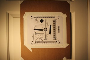
Figure 1 – The PIMA/ISO resolution target mounted on a 400 mm board to enable determining the resolution of a digital camera
Next modern digital cameras exceed the resolution of the PIMA/ISO target if you use it as originally directed. So what you need to do, as shown in Figure 1, is to mount it on a larger board. In my case, I mounted it on a 17 ‘ X 14 “ board. Note the big arrows in the corners of the target. These are 200 mm apart. The height of the board is just over 400 mm, actually 412 mm. Note next the nine lines that narrow horizontally and vertically. Here’s a paradox. The horizontal lines determine the resolution vertically and the vertical lines horizontally. What you do is simple. Place the camera on a tripod. Did I mention that the camera must be mounted on a tripod, or else your resolution will be defined by handshake. Set your camera to take raw unsharpened images. You can use unsharpened JPEG images, but as you will see in a later blog, this can kill your resolution. Set the camera distance such that the board just fills the screen. Then focus manually as carefully as you can. Blow up the image on your computer (zoom in) and determine at what value you can just distinguish the lines. Figure 2 is meant to show you this. Whether it will or not it does depends on the resolution of your computer monitor. So hopefullym you can see it and get the idea.
In the Figure 2, you, again hopefully, can see that this “just see” point falls at about 7.0. You then multiply by 200 and that gives you 1400 line widths per picture height. The original PIMA/ISO chart was meant to be read so that it just filled the screen and multiplied by 100. Where does 200 come from? Because we doubled the size of the target, this should now be twice as big or 200. My 412 mm actually makes this 206. In the next blog, we will examine a real lens using this protocol and determine how close to being pixel limited the resolution is.
This fairly straight forward procedure enables you to make a fairly sophisticated. You are freed from being victim to such statements, found in lens reviews, like “It’s very very sharp.” In the next technical blog we will use this procedure to evaluate the resolution of a real lens and see how it depends upon f-number.

